Voltage Controlled Motor Module
Demo vid : VCMM
Schematic :
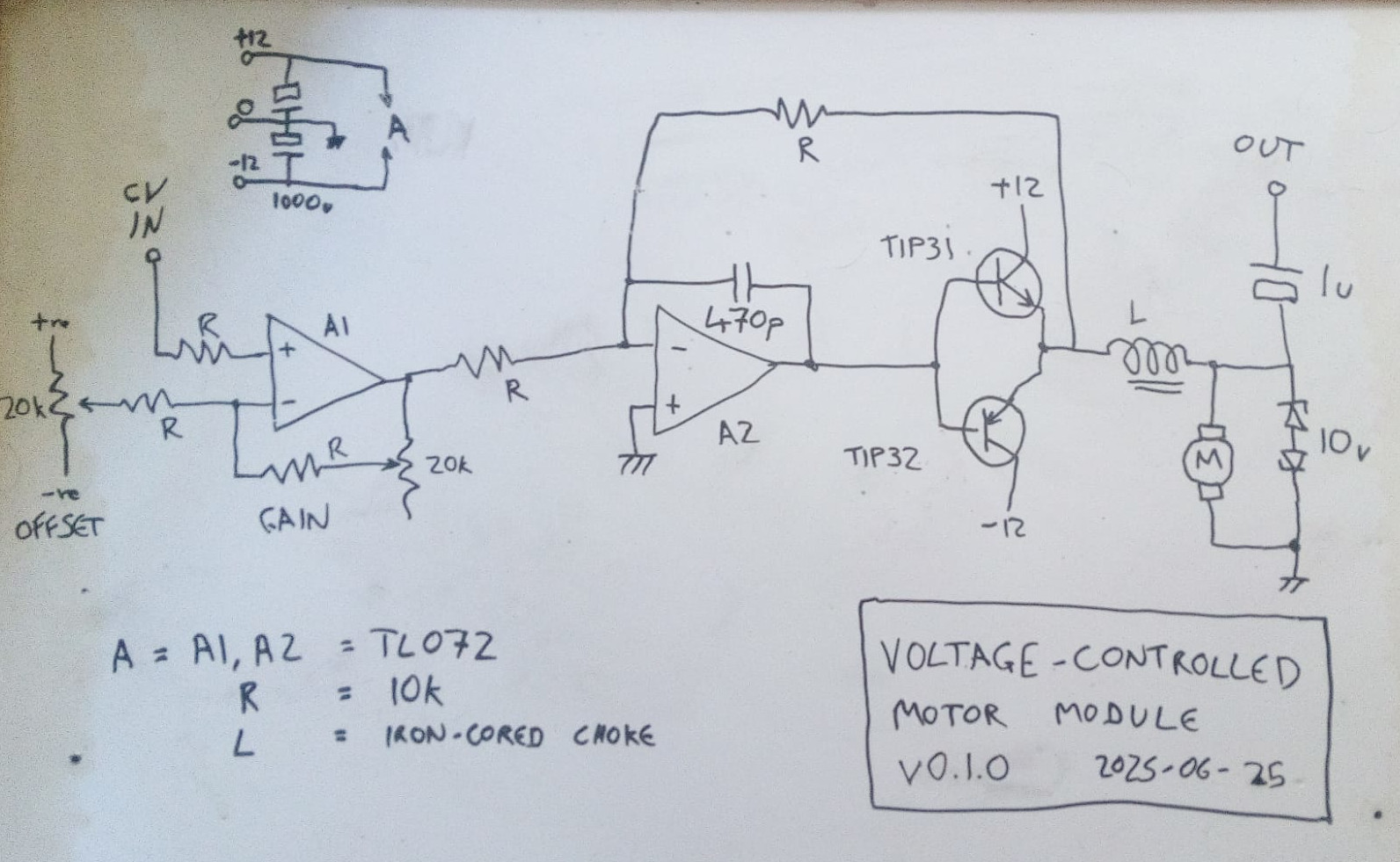
This worked on the 3rd attempt. First try, nothing happened but one transistor got hot. Then I discovered I'd got the collector wires the wrong way around. I thought I must have fried the transistors, but maybe not, after I'd replaced them I experimented a bit more. My estimate for a resistor to go in series with the motor had been way out (120R), it needed something really low. But it occurred to me that an inductance should work there, and I had a old PCB (from a satellite tuner PSU) on the desk next to me with the perfect candidate. I'd got the old board there for the 1000uF 16v caps. I didn't bother breadboarding, went straight to stripboard. It would either work or not. The components that were candidates for tweaking were easy access.
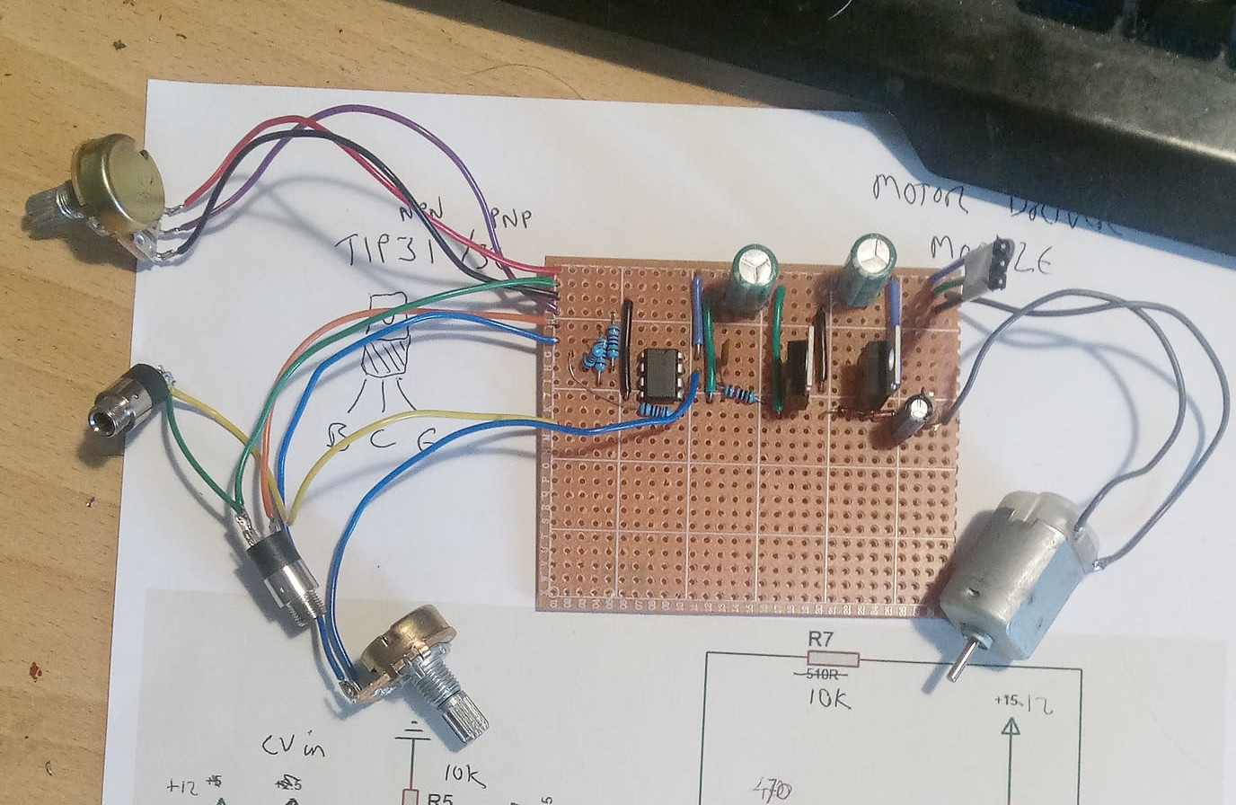
This time it actually worked. After trying it for a few seconds I felt to see if the transistors were getting warm. Burnt my fingers. Motors really aren't my thing. So I made a couple of little heatsinks and hooked it up to the modular for the vid.
I think what I'll do is try it with a PSU of its own next. With a dummy load first, to see if the circuit is behaving as I'd expected. I really don't get why it should be drawing so much current with such a farty little motor, unless the transistors are biased on when they shouldn't be. Dunno. The motor is the main unknown for me.