Simple Distortion Circuit
I was a bit frustrated not having a convenient distortion module on my setup so I designed one. After a handful of sketches and a little bit of breadboarding, this is what I came up with :
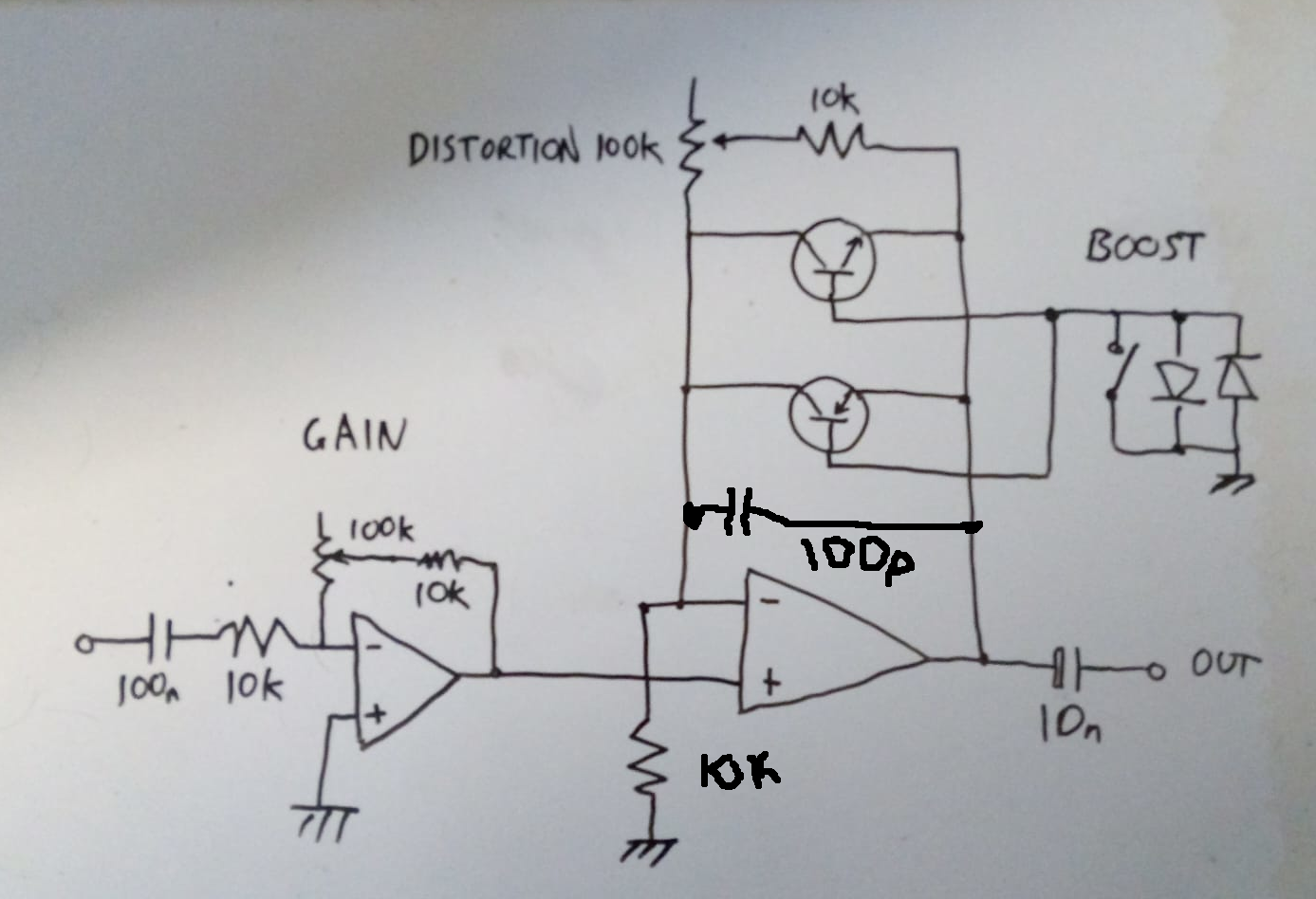
Its operation is a lot more straightforward than it looks.
The left-hand op amp is just operating as a textbook inverting amp, gain of x1 to about x10. The right-hand hand op amp is having more fun. The core idea is that of a log amplifier, the "transdiode" configuration. It's using the exponential characteristic of a bipolar transistor in the feedback of the op amp to achieve a logarithmic transfer function. In other words, soft clipping. Tube overdrive style, if you're an American guitar head. The magic part of this configuration is that the combination of NPN and PNP transistors, simply one on top of the other, actually works to make the function work on negative-going signals in mirror image. No way that would work! But it does.
I've flipped the op amp inputs so this is non-inverting - I'd forgotten, I was going to make the input amp non-inverting too... Reason being, ideally I wanted it DC-coupled so it could be an interesting function on control voltages too. But when wired up to modules this messed up its use on signals - the your guess is as good as mine Eurorack standard voltage levels. So I AC coupled it, hence the cap on input & output. (The 100p cap in the feedback is my cargo cult attempt at ensuring HF stability. It makes no audible difference).
The variable resistance in the feedback effectively adjusts when the transistors start getting curvy. When it's down to the 10k I couldn't see or hear any difference from the input signal, is effectively unity gain. Wide open, the curve starts early, it sounds like hard clipping.
The pair of diodes was the result of messing about. I initially tried them from the signal path between the first op amp and the second, to ground. I expected a buzzier hard clipping at a lower level, until the log-ish follower was wound up for gain. But it wasn't very interesting. What was interesting is the current config. I'll leave it to someone better at sums than me to figure out properly, but intuitively I would have expected this to have extended the linearish low level region up by the voltage drop until transistor bias starts kicking in, with the effect of raising the curvy roof. Nah. The result in practice is that it gives an audible boost overall. When the bases are direct to ground, the transfer curve seems rather kinky, not as smooth as it should be. With the diodes in circuit, it have a much more elegant curve. My technical explanation is something something op amp compensating something bias something.
Here's it on the breadboard :
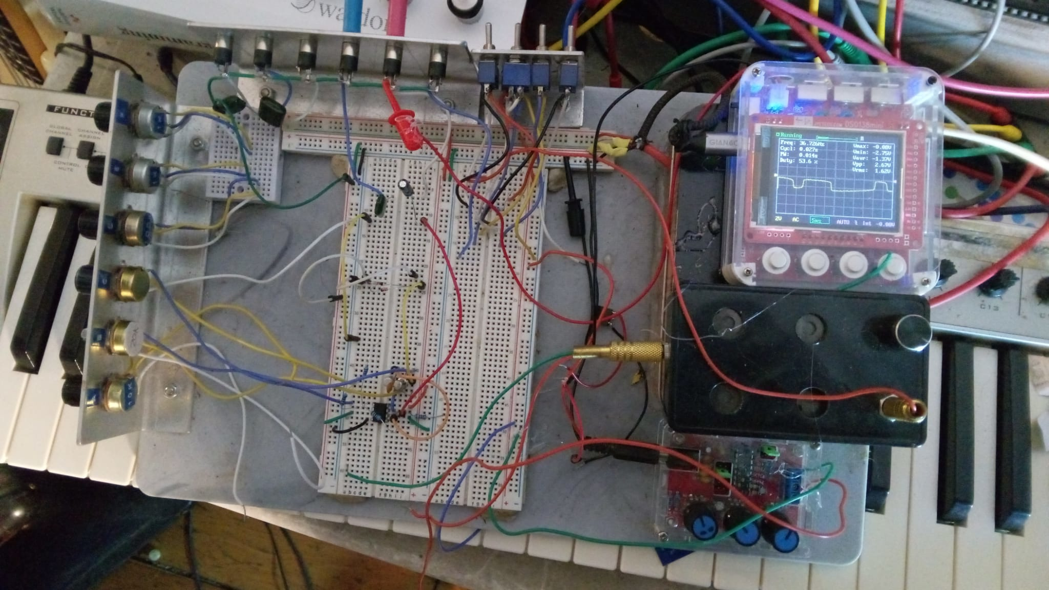
I've got all the music room gear in the office while I redecorate, and the desktop machine I usually run a 'scope (Bitscope) on was busy entertaining Claude. So it gave me a chance to use my breadboard. It is literally built on a plastic breadboard, hat tip to the originators. As well as the horrid little Chinese scope and signal generator there's a home-hack audio amp, underneath a +/- 12v, +5 PSU in a tin I got from Penny Market. Got 3.5 mm sockets, various pots, a few switches. The idea is I can take prototypes to the modular in a Mohammed-mountain kind of deal. Only after I'd made it did I hear about the Erica Synths (they who do collabs with the wonderful DIYer Moritz Klein) do a ready-made, neat version : the EDU DIY Labor. Hey ho. Saved meself a few quid.
Oh yeah, back to the circuit. Nothing's critical. For op amps I used a TL072, transistors a BC109 & BC179, generic highish gain silicon small signal I happened to have. To keep it balanced up & down you probably want a complementary pair like that. I plan to slap the circuit on a scrap of stripboard, cut & drill a bit of aluminium sheet for front panel, couple of hours work max, my itch scratched.